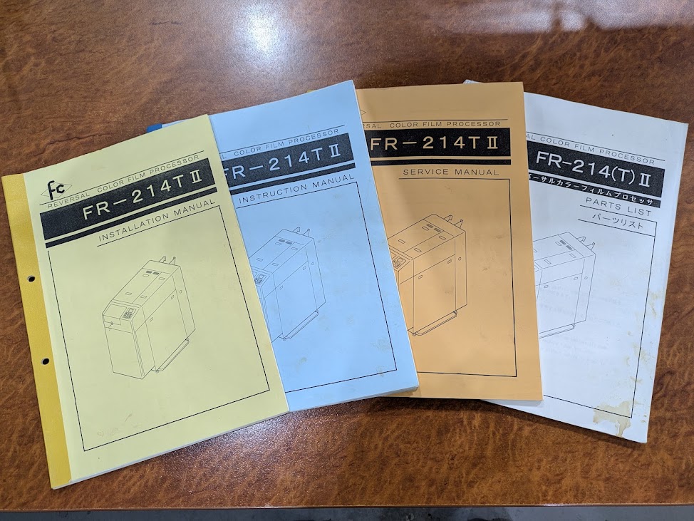
FC REVERSAL FR 214T II E6 FILM PROCESSOR




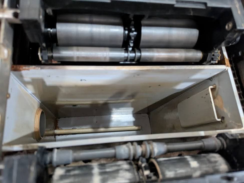
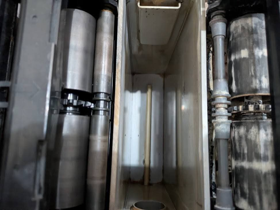

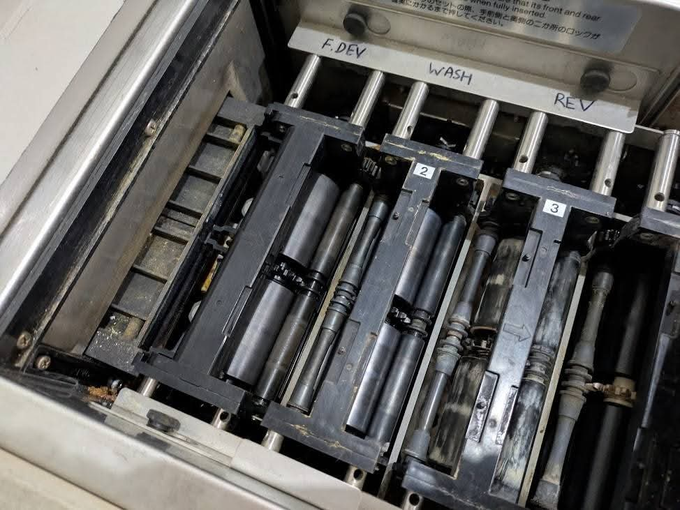


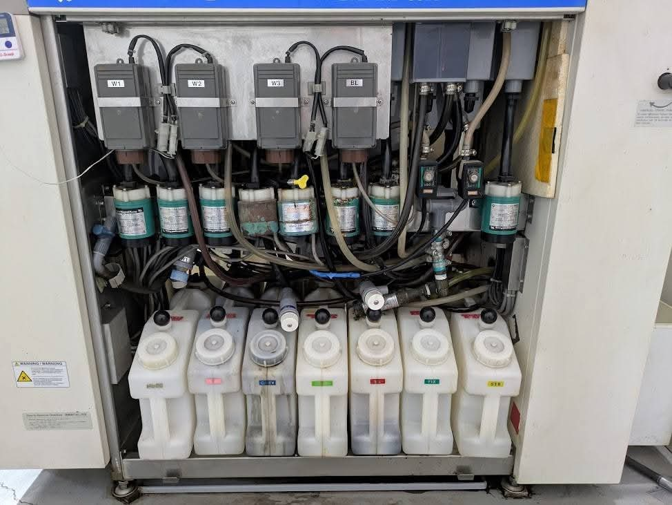

FC REVERSAL FR 214T II E6 FILM PROCESSOR
1. Instructions for Mixing Chemicals
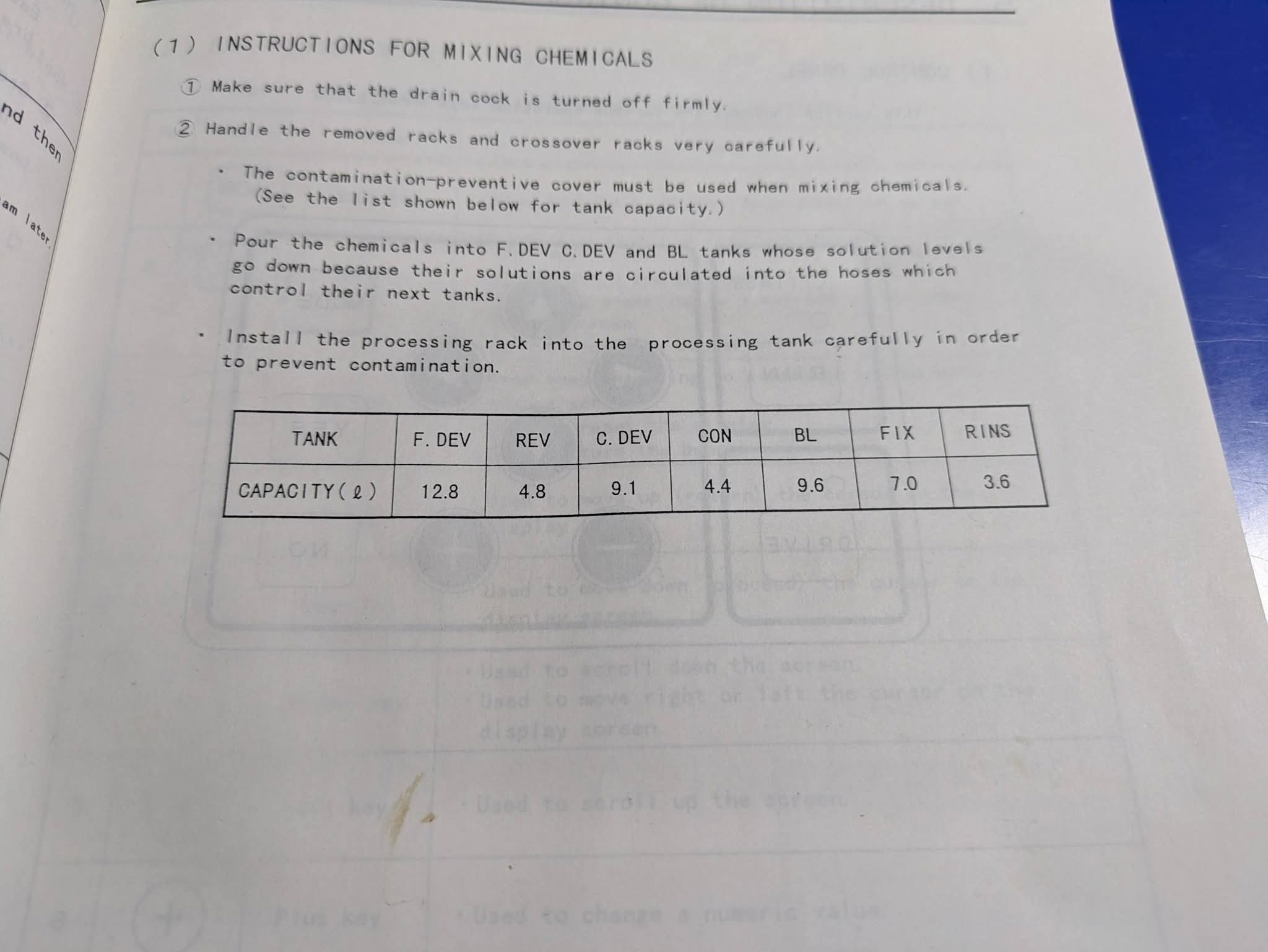
(1) INSTRUCTIONS FOR MIXING CHEMICALS
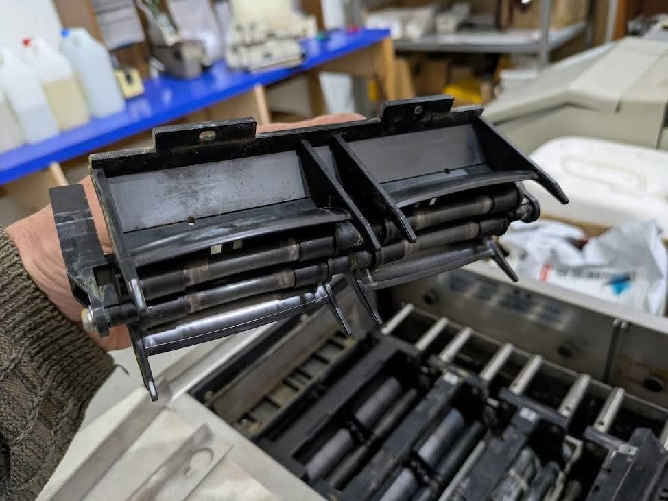
Make sure that the drain cock is turned off firmly.Handle the removed racks and crossover racks very carefully.The contamination-preventive cover must be used when mixing chemicals.
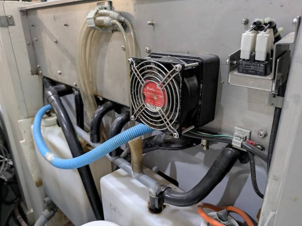
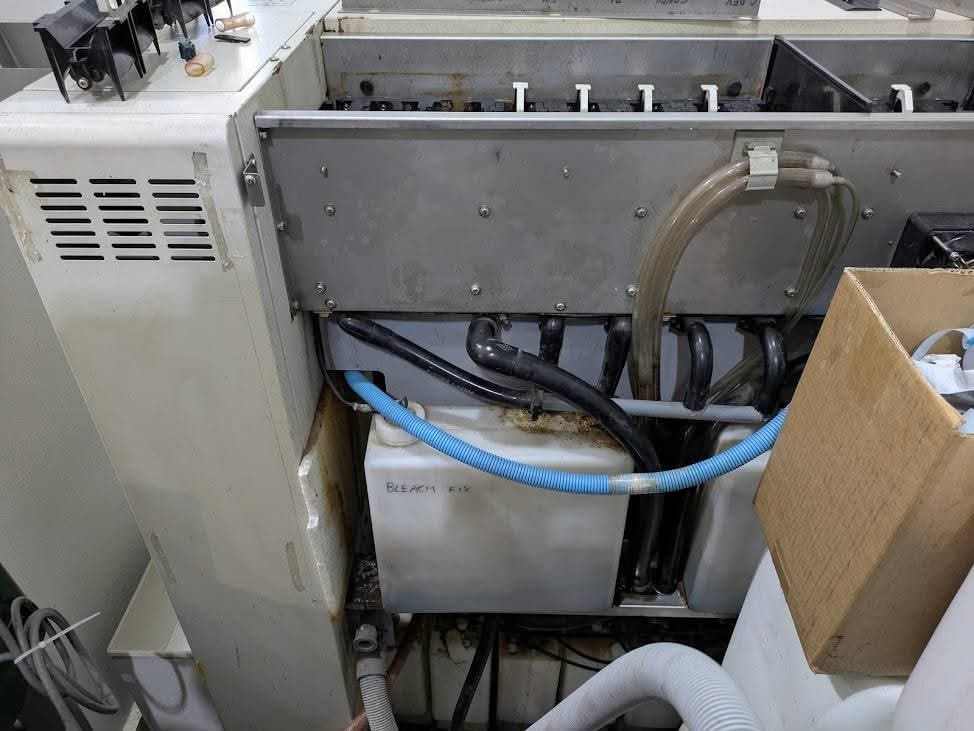
(See the list shown below for tank capacity.)Pour the chemicals into F. DEV, C. DEV and BL tanks whose solution levels go down because their solutions are circulated into the hoses which control their next tanks.Install the processing rack into the processing tank carefully in order to prevent contamination.
Tank
F. DEV
REV
C. DEV
CON
BL
FIX
RINS
Capacity (L)
12.8
4.8
9.1
4.4
9.6
7.0
3.6
2. E-6 Main Specifications
4. SPECIFICATIONS
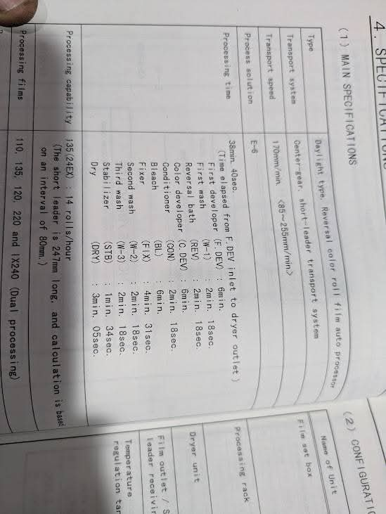
(1) MAIN SPECIFICATIONS
Type: Daylight type, Reversal color roll film auto processor
Transport system: Center-gear, short-leader transport system
Transport speed:
170 mm/min. (85–255 mm/min.)
Process solution:
E-6
Processing time:
38 min. 40 sec.
(Time elapsed from F. DEV inlet to dryer outlet)
Process breakdown:
Process
Code
Time
First developer
F-1
6 min. 18 sec.
First wash
F-W
2 min. 18 sec.
Reversal bath
REV
2 min. 18 sec.
Color developer
C-DEV
6 min. 18 sec.
Conditioner
CON
2 min. 18 sec.
Bleach
BL
6 min. 18 sec.
Fixer
FIX
4 min. 31 sec.
Second wash
W-2
2 min. 18 sec.
Third wash
W-3
2 min. 18 sec.
Stabilizer
STB
3 min. 05 sec.
Dry
DRY
3 min. 05 sec.
Processing capability:
135 (24EX): 14 rolls/hour
The manual notes that the short leader is 247 mm long, and the calculation is based on an 80 mm interval.
Processing films:
110, 135, 120, 220 and 1×240 (dual processing)
(3) TRANSPORT SYSTEM
Fig. 5-4
Processing rack No. 1Processing rack No. 2Processing rack No. 3Processing rack No. 4Processing rack No. 5Processing rack No. 6Processing rack No. 7Processing rack No. 8Processing rack No. 9Processing rack No. 10Dryer rackShort leader receiving hanger
Extracted from the page:
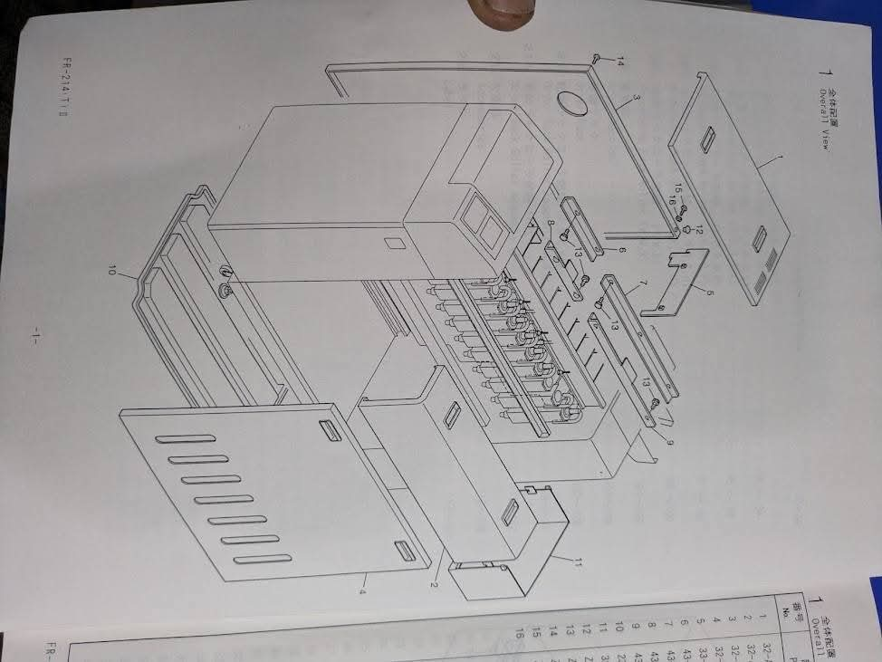
1. Overall View
Figure: Exploded overall view of the E-6 film processor.
The visible diagram identifies components by reference numbers 1–15.
From the drawing, the clearly distinguishable major assemblies include:
1. Top cover
2. Front/lower cover assembly
3. Rear panel
4. Front access panel/door
5. Bracket/plate
6. Upper mounting plate
7. Upper rail/guide
8. Fastener
9. Upper side/guide component
10. Base/frame
11. Side housing/cover
Sent from my Galaxy
Request quotation